Roberto J. Canales
Project Manager, BSME
Phase 3 Tower Exterior Repair Project
facts at a glance
Location: Walnut Creek, California
Project Start Date: August 2018
Estimated Completion: March 2020
Architect: Ratcliff Architects
Project Budget: $8 million (GMP)
Tier 1 Subcontractors: Scaffold Solutions, KHS&S, West Coast Glazing, Apex Mechanical, Contra Costa Electric, Best Contracting Services.
Section Contents:
Introduction: A New Face, A New Beginning.
The John Muir Health Walnut Creek Phase 3 tower faced a 10 year history of progressive water infiltration issues. And its location placed it squarely in the Bay Area's spot for heavy seasonal rains. This situation posed a serious problem for the facility because water infiltration often occurred in patient surgery prep or recovery areas, exacerbating the possibility of compromising delicate immune systems with a risk of exposure to black molds that often form within damp recesses of leaky building ceilings or walls.
Swinerton's project scope aimed to replace leaking exterior cladding, windows, exterior framing, damaged roofing, and contain and remove any materials found to be contaminated with black mold. The project was broken down into 9 Phases; Phase 1-7: New Exterior Windows and Cladding Install, Phase 8: two nurse staff lounge remodels, and Phase 9a and 9b: Damaged/leaking roof repair.
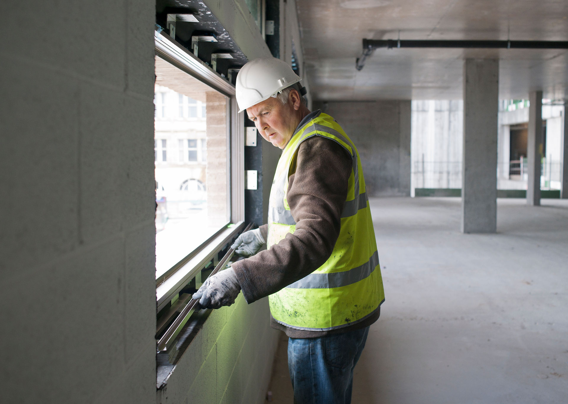
1. Exterior Framing and Window Systems
It is necessary to give a brief overview of exterior framing configurations and their interactions with building architectural features such as windows and exterior cladding or insulating foam systems.
John Muir Health Walnut Creek Phase 3 tower implements a spandrel framing system with a slip track system at the 'head' of the window that allows a degree of deflection of the framing system in case of seismic or high wind load situations.
With the commonality of ribbon windows and punched windows along the periphery of the Phase 3 tower, it becomes essential to understand the structural requirements per the building's original design so that existing rust damaged windows and exterior framing are completely replaced without compromising the structural integrity and ability for in-plane movement of the spandrel framing as intended by the original design.

Figure 1.1 - In plane movement of the spandrel framed system is depicted in the figure to the right, this system comprises of a floor to window head comp channel allowing for in plane movement.

Figure 1.2 - Out of plane movement is common for the slotted track system, as depicted in the figure on the left. Per 2003 International Building Code (ASCE 7.9.6.2.4) framing systems are to allow for 6 degree of freedom displacement in the event of seismic or high wind load situations. Depending on the particular building design, deflection may be as great as 2-3 in.
_edited.jpg)
Figure 1.3 - Contract document detail depicting the slip track. A 'nested track within a track' is a typical system utilized to provide deflection capability to the exterior framing at the window head.
2. Engineered Scaffolding
A full scaffolding system was required for the whole project. This system would have upwards of 200 lbs. per square foot load at any given time, along with constant wind loading. The system was to be completely enclosed in thermo plastic to keep inclement weather out on any given day. As the scaffolding would directly serve occupied floors, it was paramount to keep outside moisture from getting into the building and causing unwanted damage. The scaffolding included 2 stair towers, 3 material hoists, and it's custom designed trash chutes.


Figure 2.1 - Top Left: Stair Tower 3 with ladder access to 3rd floor scaffolding located between the Phase 3 and Phase 4 buildings courtyard. Bottom Left: Stair Tower 3 and courtyard view from the helicopter pad on top of Phase 4 building. Right: Stair Tower 1, main access tower located adjacent to the Ambulance Emergency department.
3. Infectious Control Methods
Given the sensitive nature of the work areas, it was paramount for the project team to keep adequate controls in place to significantly reduce the risk of contaminating patients in adjacent work areas. Plastic barriers, air scrubbers, sticky mats, and 24 hour sanitary crew rotations were in order for more than 10 departments spanning 5 floors.

Figure 3.1 - Infection Control Plan snapshot for construction activity phase 7 involving the Phase 3 Tower 5th floor exterior cladding and windows demolition and installation. Equipment symbology is indicated in the legend and can be seen distributed strategically within the negative pressure containment zone inside the patient rooms.


Figure 3.2 - Left: Patient rooms sealed off from use during the exterior demolition phases. Rooms are kept zipped closed with medical grade containment barriers. Center: Anteroom containment within a work room. The temporary Anteroom is designed to keep moisture, debris, and dust from contaminating the entirety of the hospital room. Right: HEPA filter, negative pressure vacuum, and sticky mats are kept within the Anteroom. Double zipper ingress/egress accessways can be seen here.
4. Demolition and Installation Activities
The system meant to replace the existing weather damaged stucco and tile system would be the lighter and moisture tight exterior insulating foam system. New technology and construction practices allowed for this system to make a comeback in recent years. The demolition of the exterior window framing system along with the exterior cladding was no small feat, as it required heavy coordination with hospital staff.

Figure 4.1 - Depiction of all nine exterior work phases. Phases 1 through 7 involved the demolition exterior cladding and existing windows, repairing and/or replacing water damaged exterior framing, and the installation of new EIFS and Aluminum Ribbon and Punched windows. Phase 8 involved replacing existing parapet flashing and grating with new aluminum grating. Phase 9a and 9b involved repairing damaged Phase 4 tower roofing membranes.


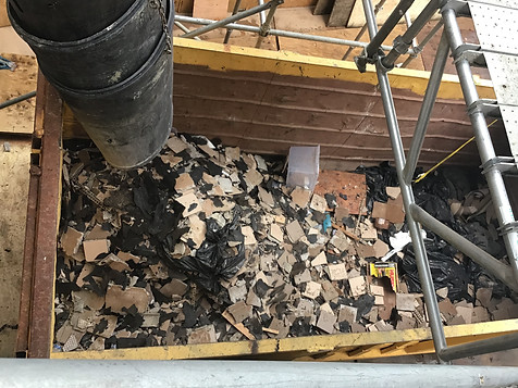

Figure 4.2 - Exterior cladding demolition activities underway. Existing cladding consisted of ceramic tile and sparse building joints running horizontally and vertically throughout the Phase 4 cladding. It was found that many of the building joints had become weathered and were letting in moisture into the building.


Figure 4.3 - Above: Interior insulation foam and densglass installation on construction phase 2. Below: Application of Class 1 vapor retarder system Backstop NT from Dryvit. One coat is applied over densglass joints and drill holes, followed by a coat of the whole exterior section. Then, Dryvit Aquaflash liquid adhesive sealant system (shown in black) is applied around the head, jamb, and sills of the rough window openings to provide further moisture protection before the installation of the aluminum window systems.


Figure 4.4 - Top Left: Slip track system at the rough head of ribbon window opening. Top Middle: Dryvit Aquaflash waterproofing applied at the head, jambs, and sills of the ribbon window rough opening. Top Right: West Coast Glazing installing ribbon window aluminum jamb at construction phase 2. Bottom Left: Installation of the ribbon window sill bottom track. Caulk sealant is seen applied over the fasteners drilled through the track securing it to the window framing. Middle Right: Ribbon window installation complete prior to installation of exterior insulation foam system.
Bottom Right: Demolition of existing ribbon windows on construction phase 3. Notice rust corrosion at the head framing. Corroded framing was torn out and fresh galvanized framing was installed.
5. Mock-Ups and Water Leak Testing
Given that the John Muir Health hospital had a bad history of water infiltration on the Phase 3 tower, the project team wanted to ensure the installation that was to remediate those very same issues was sound and devoid of any defects. Given this mode of thinking, Swinerton took it upon themselves to water test 100% of all newly installed windows.


Figure 5.1 - Top: Air and Water Testing Rig set-up at construction phase 1, 2nd floor ribbon window. Bottom: Checking for water leaks as leak testing is underway. Reference the water leak testing reports below for results.